What a Crosshead Actually Does in Cable Extrusion
The crosshead is where a bare conductor becomes an insulated cable. Here is how it works, why concentricity matters, and what separates a good crosshead from a troublesome one.
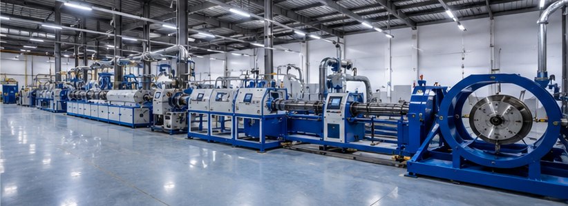
If you follow a bare copper or aluminium conductor through a cable line, the moment it becomes a cable happens inside one component: the crosshead. It is a modest-looking block of steel bolted to the front of the extruder, and it does something quietly clever — it turns the horizontal flow of molten polymer through ninety degrees and wraps it evenly around a wire moving through its centre.
Turning the melt around the wire
An extruder pushes molten plastic straight ahead. But the conductor runs across that flow, perpendicular to the screw. The crosshead’s job is to redirect the melt so it flows around the wire and closes up behind it as a seamless tube of insulation.
Inside, the key parts are:
- The die — the outer ring that sets the outside diameter of the insulated cable.
- The tip (or guider) — the inner nozzle the conductor passes through, setting the inside boundary of the plastic.
- The flow channels — carefully shaped passages that split the incoming melt and bring it evenly around the full circumference before it meets the wire.
Get that flow distribution right and the plastic arrives uniformly all the way around. Get it wrong and one side is thicker than the other.
Why concentricity is everything
The single most important quality measure at the crosshead is concentricity — whether the conductor sits perfectly centred inside the insulation. If the wire drifts off-centre, one side of the insulation is thin and the other is thick.
That matters for real reasons:
- Electrical safety. The thin side has reduced dielectric strength — the first place a cable is likely to fail under voltage.
- Material cost. Over-thick insulation on the other side is wasted polymer, run after run, tonne after tonne.
- Standards compliance. Cable specifications set minimum wall and eccentricity limits that simply must be met.
Good crossheads allow fine centering adjustment — traditionally with adjusting bolts, and increasingly with self-centering tooling — so the operator can dial the wire dead-centre and hold it there. The best explanations of the trade-offs come from the crosshead designs used on production wire and cable lines, where centering, pressure and streamlining are all engineered together.
Pressure versus tubing tooling
Crossheads generally run in one of two tooling modes:
- Pressure tooling — the melt is pressed directly onto the conductor inside the die, giving a tight, void-free bond. Used for insulation that must grip the conductor.
- Tubing tooling — the plastic is formed into a tube slightly larger than the wire and drawn down onto it, sometimes with vacuum. Used for jacketing and loose coverings, and where the covering should strip easily.
Choosing between them depends on the product: primary insulation usually wants pressure tooling; an outer sheath often wants tubing tooling.
Streamlining and dead spots
Because polymers degrade if they sit hot for too long, crosshead flow channels must be streamlined — no dead corners where material can stagnate and burn. A stagnation point shows up later as black specks or gels in the insulation, which for a cable maker means scrap and complaints. A well-designed crosshead keeps every bit of melt moving smoothly from inlet to die.
The takeaway
The crosshead is small, but it decides the two things a cable is judged on: whether the insulation is the right thickness, and whether it is evenly placed around the conductor. Everything upstream (melting the polymer) and downstream (cooling, printing, spooling) exists to support what happens in that one turned-through-ninety-degrees moment. Understand the crosshead and you understand the heart of a cable line.